The group assignment for this week:
This week we examined the following input device:
The ICS43434 is a digital MEMS (Micro-Electro-Mechanical Systems) microphone from InvenSense. Unlike analog microphones, it communicates using the I2S (Inter-IC Sound) protocol, which sends audio data as a digital serial bitstream rather than a varying voltage.
MEMS microphones contain a tiny mechanical diaphragm etched into a silicon chip. When sound waves hit the diaphragm, the capacitance changes, and the integrated ADC converts this into a digital signal. This makes MEMS microphones small, low-power, and consistent in performance across units.
| Pin | Function |
|---|---|
| 3V | Power supply (3.3V) |
| GND | Ground |
| BCLK | Bit Clock — serial clock that drives data transmission |
| DOUT | Data Output — serial audio data from the microphone |
| LRCLK | Word Select / Left-Right Clock — distinguishes left/right channel frames |
| SEL | Channel Select — GND = Left channel, 3V = Right channel |
I2S (Inter-IC Sound) is a synchronous serial communication protocol designed specifically for digital audio. It differs from I2C and SPI in that it is optimized for continuous high-throughput audio streaming rather than short control messages.
Three wires carry the signal:
Because I2S uses a dedicated clock line, the sender and receiver do not need to agree on a baud rate in advance, unlike UART. The clock keeps both sides synchronized automatically.
One important consequence of the ICS43434 being a fully digital sensor: there is no analog voltage to probe with a multimeter. A standard multimeter cannot accurately measure signals above approximately 1 kHz, so probing BCLK at 2.8 MHz will always read close to 0V even when the signal is healthy. The correct tool for measuring these signals is a logic analyzer.
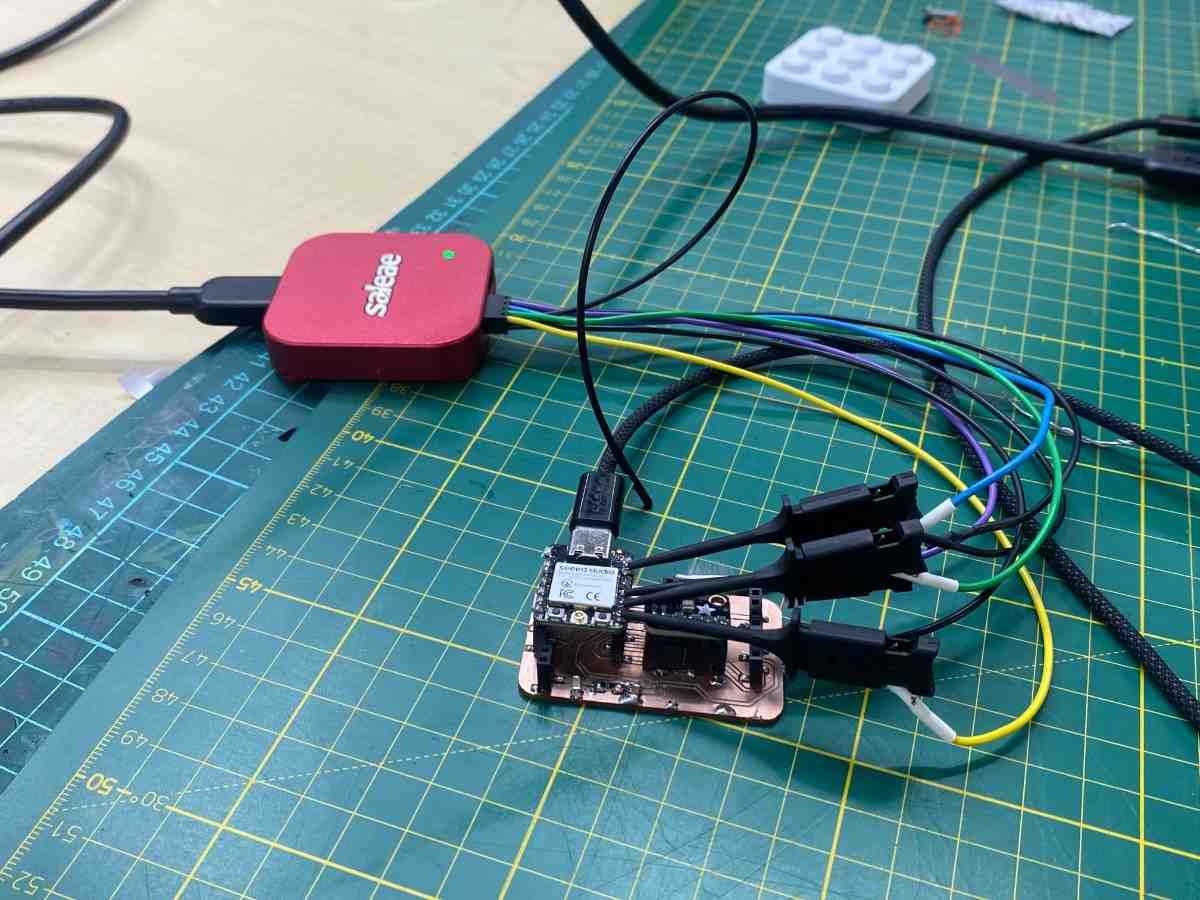
We used the Xiao ESP32-C3 (Seeed Studio) to drive the microphone and the Saleae Logic Pro 8 to capture and decode the signals.
| PCB Pin | Signal | GPIO |
|---|---|---|
| 12 | PWR_3V3 | — |
| 13 | PWR_GND | — |
| 9 | BCLK | GPIO8 |
| 10 | LRCL | GPIO9 |
| 8 | DOUT | GPIO20 |
The SEL pin is tied to GND on the PCB, fixing the microphone to the Left channel.
The Saleae probes were connected directly to the PCB connector pins using grabber clips. Because the pads are tightly spaced, we used short jumper wires pushed into the connector holes as extension points for the clips, preventing adjacent pins from being shorted by the wide clip jaws.
We wrote the following Arduino sketch for the Xiao ESP32-C3 to drive the I2S peripheral and output audio samples over Serial:
#include <driver/i2s.h>

// PCB pin 9  = BCLK = GPIO8
// PCB pin 10 = LRCL = GPIO9
// PCB pin 8  = DOUT = GPIO20

#define I2S_SCK_PIN   8
#define I2S_WS_PIN    9
#define I2S_DATA_PIN  20

#define SAMPLE_RATE  44100
#define BUFFER_LEN   512

int32_t samples[BUFFER_LEN];

void setup() {
  Serial.begin(115200);
  delay(2000);

  i2s_config_t config = {
    .mode                 = (i2s_mode_t)(I2S_MODE_MASTER | I2S_MODE_RX),
    .sample_rate          = SAMPLE_RATE,
    .bits_per_sample      = I2S_BITS_PER_SAMPLE_32BIT,
    .channel_format       = I2S_CHANNEL_FMT_ONLY_LEFT,
    .communication_format = I2S_COMM_FORMAT_STAND_I2S,
    .intr_alloc_flags     = ESP_INTR_FLAG_LEVEL1,
    .dma_buf_count        = 8,
    .dma_buf_len          = BUFFER_LEN,
    .use_apll             = false,
  };

  i2s_pin_config_t pins = {
    .bck_io_num    = I2S_SCK_PIN,
    .ws_io_num     = I2S_WS_PIN,
    .data_out_num  = I2S_PIN_NO_CHANGE,
    .data_in_num   = I2S_DATA_PIN,
  };

  i2s_driver_install(I2S_NUM_0, &config, 0, NULL);
  i2s_set_pin(I2S_NUM_0, &pins);
  i2s_zero_dma_buffer(I2S_NUM_0);

  Serial.println("ready");
}

void loop() {
  size_t bytes_read = 0;
  i2s_read(I2S_NUM_0, samples, sizeof(samples), &bytes_read, portMAX_DELAY);

  int count = bytes_read / sizeof(int32_t);
  for (int i = 0; i < count; i++) {
    int32_t s = samples[i] >> 8;
    Serial.print("mic:");
    Serial.println(s);
  }
}
The i2s_read() function blocks until a full DMA buffer of samples is ready, then returns all of them at once. This guarantees uninterrupted continuous recording with no gaps between reads. Each 32-bit sample is right-shifted by 8 bits to extract the meaningful 24-bit audio value from the ICS43434's MSB-justified output format.
With the sketch running on the ESP32-C3, we captured the I2S signals using the Saleae Logic Pro 8 and Logic 2 software. We configured an I2S/PCM analyzer with:
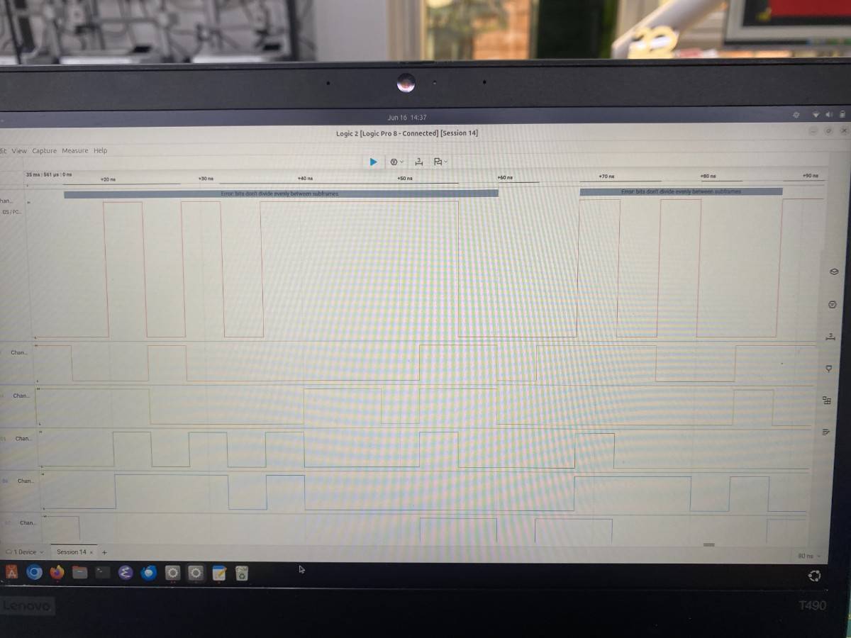
The capture clearly shows all three I2S signals active and switching:
The Logic 2 I2S/PCM analyzer flagged "Error: bits don't divide evenly between subframes". This is a known message that appears when the analyzer's subframe division setting does not exactly match the device's frame structure — it does not indicate a hardware fault. The signals themselves are clean and correctly timed, confirming the microphone and ESP32-C3 are communicating properly over I2S.
This result confirms:
| Property | Value |
|---|---|
| Sensor | ICS43434 MEMS Microphone |
| Protocol | I2S (Inter-IC Sound) |
| Supply voltage | 3.3V |
| Bit depth | 24-bit in 32-bit frame |
| Sample rate | 44100 Hz |
| BCLK frequency | ~2.8 MHz |
| BCLK GPIO | GPIO8 (PCB pin 9) |
| LRCLK GPIO | GPIO9 (PCB pin 10) |
| DOUT GPIO | GPIO20 (PCB pin 8) |
| Logic analyzer | Saleae Logic Pro 8 |
The ICS43434 is a fully digital sensor — all audio leaves the chip as a serial bitstream. Unlike the analog sensors examined in previous weeks, there is no analog voltage level to probe. Instead, a logic analyzer is required to observe and decode the digital protocol. The Logic 2 capture confirmed that the I2S signals were present, correctly timed, and actively carrying audio data from the microphone to the microcontroller.